
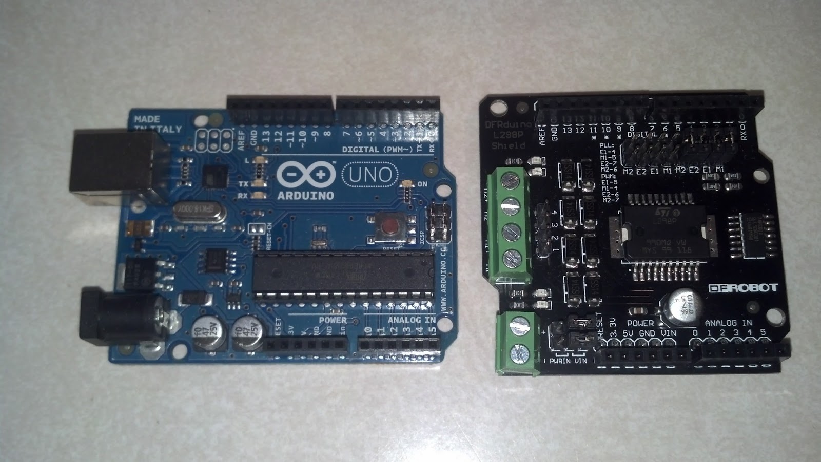
 This simple robotics platform was built from a radio controlled vehicle that can be purchased online for about $20 or less (check your favorite toy shops). The electronics added at this stage include an Arduino UNO and a top mounted DFRobot L298P Motor Shield. These items should cost around $30 for the Arduino and under $20 for the motor shield. Both of these components, their datasheets, tutorials and sample code are available from a variety of online sources including Adafruit, Digi-key, and SparkFun.
The process began with the slow deconstruction of the toy vehicle and the careful saving of all the screws, springs, and tiny structural pieces. It was soon found that this little vehicle employs just two small, low current, electric motors. One motor is used for driving the rear wheels and the other is used for steering the front end. Having just two motors is fortunate because the particular Arduino shield being used has the capacity to control precisely two motors of this type.

 Once the existing controller board was located and removed, it was replaced with a sturdy wiring harness that was designed to bring the motor control lines and battery power to the outside of the vehicle. The harness was then connected to a terminal block that had been secured to a central location on the top of the vehicle's body using double-sided tape. A second set of wires was then routed from the terminal block to the rear of the toy vehicle where it was connected directly to the Arduino and the motor shield. Being that this toy vehicle mimics the body style of a classic all-terrain utility vehicle, it has a convenient "bed" area at the rear which offers a perfect place to secure the Arduino and its attached motor shield.
 Initially, there was no intention to preserve the vehicle's outer body or existing LED lighting. However, because the toy was easily disassembled, saving these pieces became an option. There are LED headlights on the front of the vehicle as well as very bright overhead spotlights on the roll bar. At this time, all of these LED's are connected in series to pin 13 of the Arduino. Simple digitalWrite() instructions in the Arduino code allow for versatile control of these surprisingly bright LED's. In the future, the overhead spotlights and the front headlights may be given their own separate control lines so they can be used independently. There are also red LED's that serve as backup lights but those are not connected at this time.
 The software currently loops through a familiar design pattern which can be described as "scan/plan/animate". At this time, the data gathered during the "scan" phase is actually simulated by generating random values for the sensor readings. This allows the "plan" and "animate" phases to be developed in the absence of real sensors. As can be expected, the resulting behavior can be rather chaotic but it certainly provides for a lively demonstration!
In future posts I will be adding a set of ultrasonic and infrared distance rangers that will be used to sense the environment and provide the feedback required to support autonomous and intelligent behavior.
Reproducing this project can be a great way to get started on your own autonomous rover designs. Follow the links below for hardware resources, the Arduino IDE, and the source code used in this project.
SOFTWARE RESOURCES
ArduinoSafari_X1_Instrumented.ino
ArduinoSafari_X1_Instrumented.txt
Arduino IDE from Arduino.cc
HARDWARE RESOURCES
Arduino UNO R3
DFRobot L298P Motor Shield
RC Safari Vehicles
Please feel free to post comments, questions, suggestions and concerns in the space provided.
Thanks for visiting!
Build something! You can do it!
Awesome lamp. : )
ReplyDelete